Welcome to the most critical stage of your solar journey. You’ve chosen your panels, selected an inverter, and planned your location. Now, it’s time to connect everything. While it might seem like simply plugging in cables, solar panel wiring is a science. Done correctly, it ensures your system is safe, efficient, and will generate maximum power for decades. Done incorrectly, it can lead to significant power loss, damaged equipment, and serious safety hazards like electrical shocks and fire.
Our mission at Vecharged is to empower you with the clarity needed to tackle this project confidently. This guide will demystify the process of solar panel wiring, transforming complexity into a clear, step-by-step plan. We will cover the fundamental principles, the critical components, and the non-negotiable safety procedures you must follow.
Disclaimer:This guide is for educational purposes. Working with solar electricity is dangerous. Always adhere to local electrical codes, permitting requirements, and safety standards like the National Electrical Code (NEC). If you are ever in doubt, consult a licensed electrician.
1. The Three Fundamental Wiring Configurations
Every solar panel array, from a two-panel setup on an RV to a multi-kilowatt home system, is built on three basic wiring concepts. Understanding how they work is essential to designing a system that meets the voltage requirements of your charge controller or inverter and the power goals of your home.
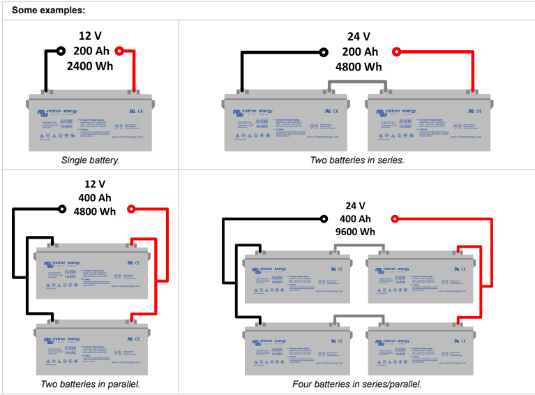
A) Series Wiring: The Voltage Builder
In a series connection, you connect the positive (+) terminal of one solar panel to the negative (-) terminal of the next. Think of it like stacking batteries in a flashlight; you are daisy-chaining them together in a single line, known as a “string.”
How it Works: The voltages (Volts) of each panel add up, while the current (Amps) stays the same as that of a single panel.
Example: If you connect two 12-Volt, 5-Amp panels in series, the result is a 24-Volt, 5-Amp system.
Primary Use: This is the most common method for increasing the total voltage of a panel string to meet the specific input voltage window required by modern MPPT (Maximum Power Point Tracking) charge controllers and grid-tied inverters.
B) Parallel Wiring: The Current Builder
In a parallel connection, you connect all the positive (+) terminals from multiple panels together and all the negative (-) terminals together, typically using specialized “branch connectors” (often called Y-connectors). Think of this as adding more lanes to a highway; you aren’t increasing the speed limit (voltage), but you are increasing the amount of traffic (current) that can flow.
How it Works: The current (Amps) of each panel adds up, while the voltage (Volts) stays the same as that of a single panel.
Example: If you connect two 12-Volt, 5-Amp panels in parallel, the result is a 12-Volt, 10-Amp system.
Primary Use: To increase the total amperage of your solar array. This is common in smaller 12V or 24V off-grid systems where you need more power without exceeding the charge controller’s voltage limit.
C) Series-Parallel Wiring: The Hybrid Approach
For larger or more complex systems, you will often need to combine both methods. This involves creating multiple, identical strings of series-connected panels, and then joining those individual strings together in parallel.
How it Works: This configuration allows you to increase both the voltage and the current simultaneously, giving you precise control over the array’s final output.
Example: Using four 12-Volt, 5-Amp panels, you could create two separate series strings of two panels each. Each string would be 24-Volts at 5-Amps. When you connect these two strings in parallel, the final output is a 24-Volt, 10-Amp system.
Primary Use: Essential for building larger, high-wattage arrays that precisely match the input specifications of a powerful inverter or charge controller.
2. Sizing Your Wires: The Most Common—and Dangerous—DIY Mistake
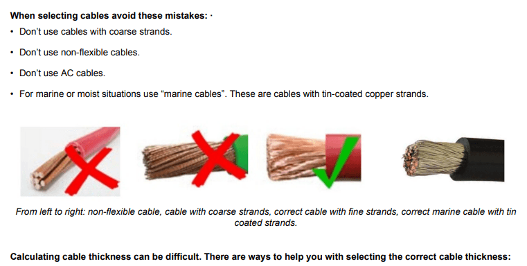
This is where theory meets reality. Using an undersized wire (or “cable”) is one of the most frequent and hazardous errors in DIY solar. The wire gauge you choose must be able to handle the system’s current safely and efficiently.
There are two primary factors to consider:
Ampacity: This is the maximum current a conductor can handle before it overheats. A wire that is too thin for the current passing through it will get dangerously hot, which wastes precious energy and can melt the insulation, creating a severe fire risk.
Voltage Drop: All wires have a small amount of electrical resistance. Over a distance, this resistance causes a loss of voltage. If the wire is too thin or the run is too long, this voltage drop can become significant, causing your system to underperform because the inverter or charge controller isn’t receiving the full energy generated by your panels. We always aim for a voltage drop of 3% or less.
The Vecharged Wire Architect
While you can use online calculators and reference charts, we are developing the “Vecharged Wire Architect,” our first niche SaaS tool. This solar wiring and safety calculator will allow you to input your panel specs, system layout, and component details to get an instant, precise recommendation for the exact wire gauges and fuse sizes you need, ensuring your system is both safe and optimized. Stay tuned for its launch.
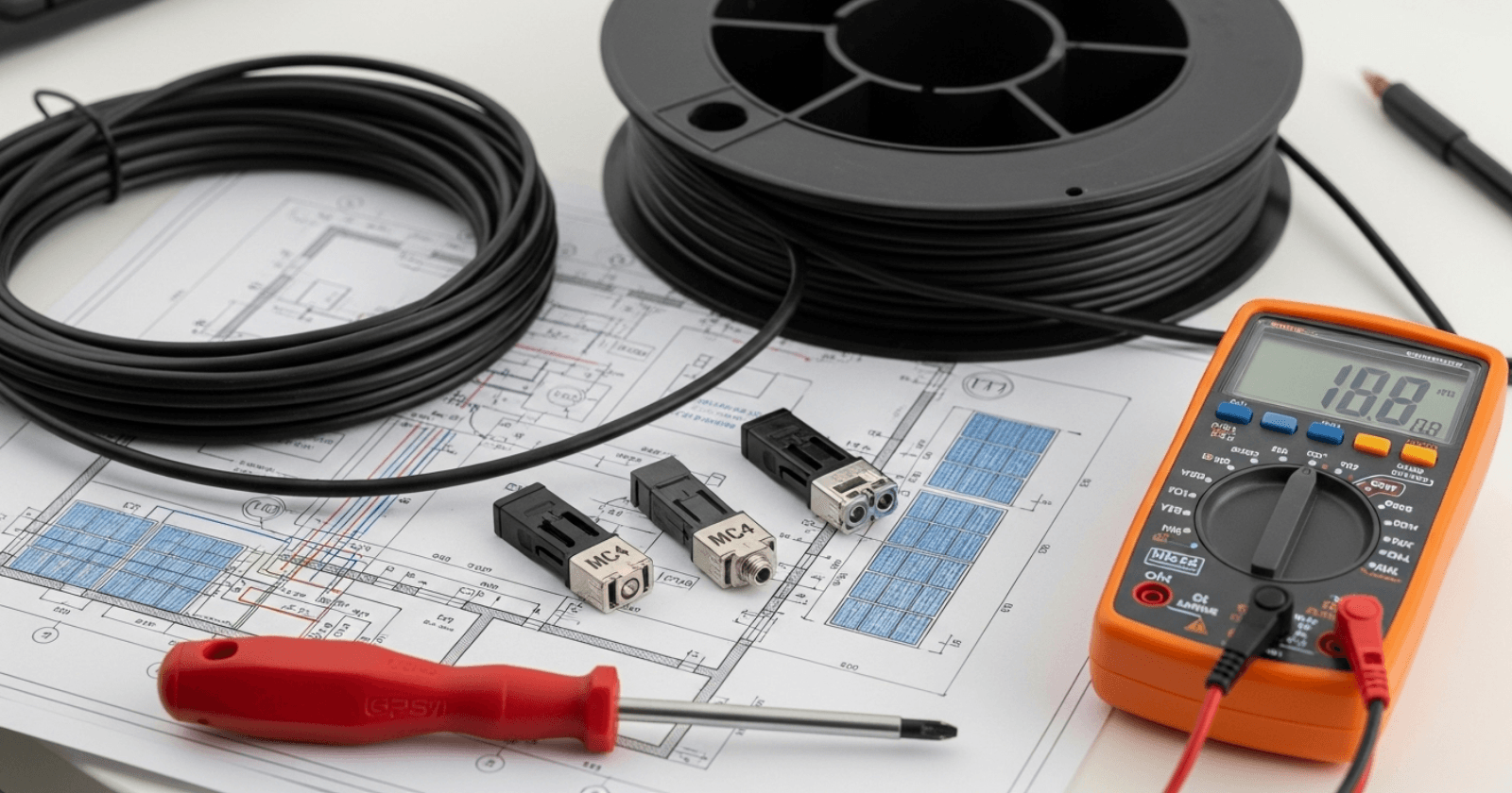
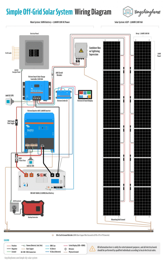
3. Essential Components for a Safe and Professional Installation
Proper wiring goes beyond the panels and the cable itself. A professional, code-compliant, and safe installation relies on several key components working together.
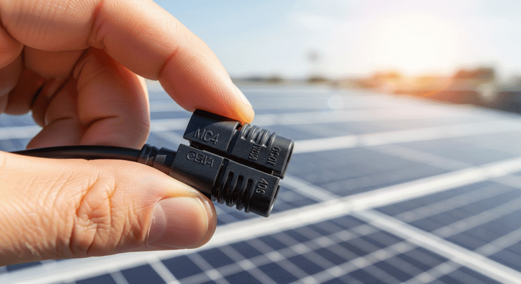
MC4 Connectors These are the industry-standard, waterproof, and UV-resistant connectors found on almost all modern solar panels. They are designed to be safe to the touch and snap-lock together, making series connections simple and reliable.
Fuses and Circuit Breakers Every part of your system must be protected from overcurrent events. A properly sized fuse or breaker is a non-negotiable safety device. If a fault occurs, it will instantly break the circuit to prevent catastrophic failure or fire. Key locations for protection include between each parallel string, between the charge controller and battery, and between the battery and inverter.
Combiner Box In systems with three or more parallel strings, a combiner box is essential. It is a weatherproof junction box where the outputs from multiple strings are safely joined (“combined”) in parallel. It also conveniently houses the fuses or circuit breakers for each string, centralizing your connections and protection into one clean, safe enclosure.
DC Disconnect Switch This is a heavy-duty safety switch that allows you to completely de-energize the power coming from the solar array before it reaches your indoor equipment. This is absolutely crucial for performing maintenance, servicing equipment, or responding to an emergency.
4. The Golden Rules: Safety First, Last, and Always
Before you touch a single wire, you must internalize these safety protocols. DC electricity from solar panels is not forgiving. It is live the moment any light hits the panels, and it presents unique risks that must be respected.
Work De-Energized: The Cardinal Rule This is the most important step. Ensure no current is flowing while you work. The only way to guarantee this is to completely cover your solar panels with an opaque material like the original cardboard box or a dark, heavy tarp. This stops them from generating voltage.
Verify with a Multimeter Never assume a wire is dead. Before you make any connection, use a quality multimeter to verify there is zero voltage (V) and zero current (A) on the conductors you are about to handle.
Follow the Correct Connection Sequence The standard, safest procedure for connecting a simple off-grid system is designed to protect your equipment:
Connect the Charge Controller to the Battery Bank first. This allows the controller to sense the battery voltage and configure itself correctly.
Connect the Solar Array to the Charge Controller.
Connect the Inverter directly to the Battery Bank.
Respect Polarity (+ and -) DC circuits have a positive (+) and a negative (-). Mismatching them (reverse polarity) can instantly and permanently destroy your charge controller, inverter, or other electronics. Double-check every single connection. Red for positive, black for negative.
Use Insulated Tools Whenever possible, use tools with certified insulated rubber handles to minimize the risk of accidental short circuits or shocks.
Never Work in the Wet Do not perform any solar wiring in the rain or on a wet roof. Water is a conductor and dramatically increases the risk of a fatal electric shock.
5. Step-by-Step Wiring Guide (A Typical Roof-Mount System)
This walkthrough assumes you have already mounted your racking and panels according to the manufacturer’s specifications and local building codes. Your panels must be covered.
Step 1: Make Your Panel-to-Panel Connections With the panels covered and verified dead, begin connecting them using their pre-attached MC4 connectors. For a series string, connect the positive (+) connector of the first panel to the negative (-) connector of the second panel, continuing this daisy chain down the line. You will be left with a single unconnected negative connector at one end of the string and a single unconnected positive connector at the other. These are your “homerun” leads.
Step 2: Run and Secure Your Homerun Wires Your homerun wires are the main PV cables that run from the solar array to your indoor equipment. Attach a properly sized PV extension cable to the positive and negative leads of your string(s). Secure these cables to the racking using UV-resistant wire clips or ties. No wire should rest directly on the roof surface.
Step 3: Connect to the DC Disconnect and Charge Controller Run the homerun wires from the array to a DC disconnect switch, and then from the switch to the PV input terminals on your charge controller. Ensure the disconnect switch is in the OFF position before making any connections. Pay meticulous attention to polarity.
Step 4: Connect the Charge Controller to the Battery Using the appropriately sized (and typically thickest) wires in your system, connect the charge controller’s battery terminals to a DC circuit breaker or fuse block. From there, connect to the main terminals of your battery bank. Make the final connection to the battery. At this point, the charge controller should power on and recognize the system voltage.
Step 5: Connect the Inverter to the Battery Using a second, separate set of heavy-gauge wires, connect your inverter directly to the same battery bank, again with a properly sized fuse or breaker on the positive line. The inverter has a high power draw and should never be wired through the charge controller’s load terminals.
Step 6: Uncover Panels and Commission the System Once all connections are tight and have been double-checked for correct polarity, you can commission the system.
Remove the opaque covering from your solar panels.
Turn on the battery breaker/disconnect for the charge controller and inverter.
Turn on the DC disconnect switch between the array and the charge controller.
Observe the charge controller’s display. It should now indicate that it is receiving power from the sun and beginning to charge the batteries. Your solar array is now live.
6. Wire Management: The Mark of a Professional
Dangling, unsecured wires are not just unsightly; they are a system failure waiting to happen. Wind, rain, snow, and animals can damage exposed cables, leading to power loss and dangerous faults.
UV Protection is Mandatory: Any wire exposed to sunlight must be a specialized, UV-resistant solar PV wire. For the highest level of protection, run these wires inside a UV-resistant, outdoor-rated conduit.
Secure All Cables: Use UV-resistant zip ties or dedicated solar wire clips to fasten all cables securely to the mounting rails at regular intervals. A professionally installed system has no loose or touching wires.
Use Drip Loops: Before a cable enters a combiner box or your home’s wall, allow it to dip down slightly before rising up into the entry point. This simple “drip loop” ensures that rainwater will drip off the bottom of the loop instead of following the cable directly into your equipment.
Expert Verdict
Proper solar panel wiring is a methodical process built on a foundation of safety and precision. The success of a DIY installation lies in meticulous planning, a deep respect for the power you are harnessing, and an unwillingness to cut corners. By understanding the core principles of wiring configurations, correctly sizing your conductors, and using the right components, you can build a system that is not only powerful but also exceptionally safe and durable. You have moved beyond being a component owner and have become a true system builder. Your mission of empowerment is complete.
Suhas Shrikant is the founder of Vecharged and an engineering enthusiast specializing in high-power off-grid solar systems. He has designed and built over a dozen custom systems and uses his hands-on, field-tested experience to create Vecharged’s expert guides and reviews.
Vecharged is the consumer protection and education initiative of Cleanpower.eco, an organization dedicated to providing a clear, unbiased, and authoritative voice in the clean energy transition. The experts at Cleanpower.eco recognized a critical crisis of trust: the shift to electric vehicles and solar power is one of the most important and expensive decisions a family will make. Yet, the landscape is flooded with biased reviews, confusing marketing, and paid-for endorsements. Vecharged was created to be the shield against that confusion. We were founded on a simple, non-negotiable constitution: We are radically independent. We accept no advertising, sponsorships, or paid placements from any product manufacturer. We have no commercial interest in the products we review. Our only metric for success is your empowerment. Our loyalty is to you, the consumer. Full stop. We ground our brutally honest, hands-on analysis in a deep, foundational understanding of the engineering. We are not just reviewers; we are your advocates.
The “Electric Revolution” in America didn’t just slow down last week; it completely redrew its map. Last week, Ford Motor Company officially confirmed a massive $19.5 billion strategic pivot, marking the most dramatic shift in the industry’s history since the launch of the Model T. In a move that has stunned the market, Ford is
The American clean energy landscape shifted on its axis on July 4, 2025. With the signing of the One Big Beautiful Bill Act (OBBBA), the rules for Solar and EV incentives were entirely rewritten. If you are a developer, fleet manager, or investor, you are no longer just in the business of energy; you are
You’re standing on the edge of a $15,000 decision, and the sales world is throwing buzzwords like “Solid-State” and “V2G” at you. Let me be blunt: most of it is noise designed to make you wait or overpay. As an expert who has been hands-on with these systems for a decade, I can tell you
Imagine turning that agonizing 2,000-foot climb into a few exhilarating minutes. That’s the e-MTB reality that has sent the US market soaring past the billion-dollar mark. The electric mountain bike (e-MTB) is no longer a niche toy—it’s the new trail conqueror, driving a market that grew from $1.05 billion in 2023 to $1.21 billion in


 Integration")